


 English
 русский
 Español
 Français
 عربى
 简体中文

Where Should Ejector Marks Be Allowed on a Storage Box?
2026-10-30
Turn a storage box over and the purchasing discussion can change. A small circular trace that is unobtrusive on a hidden underside may be unacceptable on a display face. The useful question is not whether every ejector trace can disappear. It is where marks may occur, what appearance is acceptable and how those decisions fit the part's functional needs.
This discussion belongs before the tool layout is treated as final. Toolmakers need a way to release the part, while brands and product engineers need defined surfaces and reliable assembly. A shared appearance map makes those requirements visible without promising a mark-free moulding under every process condition.
Mark the surfaces that the buyer actually sees
Use the current part drawing or a clearly identified model. On a storage box, the visible area may include the outside walls, lid-facing rim, handle region or underside shown during retail display. The relevant zones depend on how the particular product is sold and used.
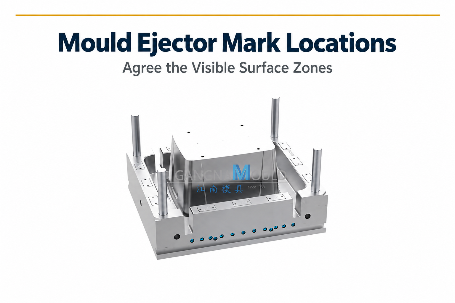
When reviewing the storage box mould range, describe those viewing conditions for the proposed part. A catalogue mould photograph cannot establish the cosmetic requirements of a new box design. Attach annotated part views that identify the face, viewing direction and relevant boundaries.
Give zones names that remain understandable through design, trial and receiving inspection. A note such as keep the front clean becomes ambiguous if different teams orient the box differently. Labels linked to drawing views are more reliable than an informal reference to the nice side.
Add functional contacts to the same map
Appearance is not the only concern. Identify surfaces that contact the lid, stack against another box, sit on a support or interact with a handle assembly. The responsible product engineer should explain any dimensional or functional limits associated with those contacts.
A mark in a visually hidden area may still matter if that area participates in stacking or assembly. Conversely, a visible region may permit a defined trace if it does not affect the intended appearance. Do not classify all underside areas as unrestricted without reviewing their role.
Keep the requirements specific enough for the toolmaker to assess. If the map creates a conflict with the proposed ejection arrangement, request an engineering discussion while alternatives can still be reviewed. Moving an ejection feature is a design decision, not a simple cosmetic edit made after steel has been finished.
Ask for the proposed ejection concept
The toolmaker should explain the intended arrangement for the actual part, including where ejection-related traces may be visible. This does not require the buyer to prescribe a particular mechanism without the necessary design knowledge. It requires the buyer to review the consequences against the agreed zones.
Storage box mould ejector marks can vary with the tool construction and moulding conditions. A drawing identifies intended locations, while samples show the outcome under documented conditions. Keep those two forms of evidence connected instead of treating either one as a complete answer by itself.
If an alternative is proposed, compare its implications for the part, tool and acceptance plan. Avoid requesting an unsupported promise that all marks will be invisible. An agreed location and a realistic appearance reference give the project a more usable basis for decision-making.
Set up an appearance-zone record
| Zone or feature | Requirement to define | Review material |
|---|---|---|
| Display face | Permitted visible traces and relevant viewing conditions | Annotated drawing and agreed sample |
| Underside | Appearance limit plus any support contacts | Part view and functional review |
| Lid interface | Relevant dimensional or mating requirements | Assembly drawing and matched parts |
| Stacking contact | Contact region and intended stack arrangement | Product design information |
| Handle region | Visible and functional restrictions | Part and assembly references |
| Proposed ejector location | Location and expected trace description | Toolmaker's concept and trial sample |
The table should not imply that every box has the same features. Remove rows that do not apply and add the contacts that matter to the current design. Its purpose is to keep the design review tied to one real part rather than a generic checklist.
Decide how trial samples will be viewed
Ejector mark acceptance needs a viewing method. Record lighting, viewing distance where relevant and whether the part is assessed alone or assembled. A strongly lit close-up can reveal a trace that is not visible in the intended presentation, while a distant photograph can hide a concern that matters in use.
Retain representative approved samples with their part and drawing references. If photographs supplement the sample, identify their orientation and avoid processing that changes the visible surface. The reference should be usable by people who did not attend the original trial.
Keep process information available for the supplier's technical review. A sample outcome should not be described as a permanent guarantee independent of material, settings or later changes. Where a requirement is not met, document the affected location and let the responsible teams review the cause and corrective proposal.
Carry the decision into production handover
Once the appearance zones are agreed, include them in the final acceptance file. A separate email approving a sample can easily become detached from the drawing used for repeat production. The supplier and buyer should know which reference takes precedence if documents differ.
Changes to texture, colour, part geometry or the ejection concept may require a renewed review. A darker or glossier presentation can change the visibility of surface traces even when the location remains the same. Treat such changes as defined revisions rather than assuming the earlier cosmetic decision automatically covers them.
- Label the actual visible faces using consistent drawing views.
- Identify lid, stacking and other functional contacts.
- Review proposed ejection locations before tooling release.
- Agree viewing conditions and representative sample references.
- Document unresolved differences by location.
- Retain the approved zone map with the production revision.
Plastic box appearance zones turn a broad request for a clean surface into a decision the project can review. Share the map with the part drawing so the toolmaker can coordinate release, function and appearance for the storage box being developed.
Previous Post
No previous article
Next Post
Injection Mould Cooling Connections: Prepare a Clear Circuit Handover
Our Products.
Quick Links
Contact Information
- ADD: No. 268, Jinchuan Road, Xinqian Street, Huangyan District, Taizhou City, Zhejiang Province, China
- TEL: +86-(0)576-89191888
- E-MAIL: gm@gangnammould.com
Mobile
Copyright © Zhejiang Huangyan Jiangnan Mould Factory All Rights Reserved.

PP Mould
