


 English
 русский
 Español
 Français
 عربى
 简体中文

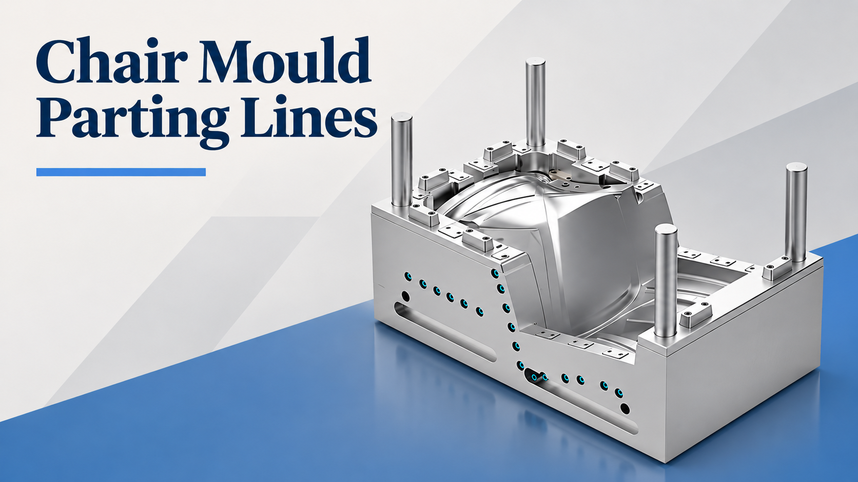
Plastic Chair Mould Parting Lines: Agree the Visible Surfaces First
2026-11-13
Before steel is cut for a plastic chair mould, someone needs to decide which surfaces a customer will notice. The seat, backrest, legs and underside do not all carry the same appearance expectations. A parting line that is acceptable underneath a seat may be unwelcome where a hand rests on the back or an arm touches the chair.
That decision belongs in the product and mould review together. It is harder to resolve after tooling has been built, particularly if the discussion began with a general request for a smooth chair. A clear surface map gives the mould designer, processor and buyer a common reference without promising that every moulding will have an invisible split line.
Put the chair drawing on the table
The JN-187 garden-chair mould shown in the Gangnam chair-mould range provides the product context for this review. It is a chair tooling project, with appearance and geometry requirements different from the storage-box projects many buyers know. Start with the intended chair design and resin rather than carrying over an old mould acceptance checklist unchanged.
Mark the front and back of the backrest, top and bottom of the seat, leg surfaces and any grip areas. Identify decorative texture, logos and intended contact points. Then review how the proposed mould split and any moving components relate to those surfaces. The supplier should explain the actual tooling concept; a photograph alone cannot establish its internal construction.
One drawing, three kinds of expectation
| Surface group | Product concern | Agreement to record |
|---|---|---|
| Prominent visible areas | Appearance under normal viewing | Inspection position and acceptable finish |
| Hand and body contact areas | Feel and accessible edges | Review method and finishing expectation |
| Hidden or underside areas | Assembly, handling and production practicality | Permitted marks and functional restrictions |
This map does not replace an engineering assessment of the chair. It organizes appearance and surface acceptance. Structural performance, stability and applicable product requirements need their own review and testing for the intended market. A well-positioned parting line is not evidence that the finished chair meets a load or safety standard.
Discuss draft and texture before polishing
The moulded chair needs to release from the tool. Draft, surface texture and the shape of ribs or openings all influence that process. A request for a particular texture should therefore be discussed before the tooling surfaces are finalized. Deep texture or an unsuitable wall orientation may change the release requirement.
Do not specify a universal draft angle for every surface in the article or purchase enquiry. The appropriate detail depends on resin, geometry, draw direction, texture and tooling design. Ask the mould maker to mark the proposed values and identify where appearance and release requirements need a compromise.
Changes can also affect the visible split. If a backrest opening, arm profile or leg shape is revised, the earlier surface map may no longer describe the right boundaries. Use controlled drawing revisions so the designer does not optimize one version while the buyer approves another.
Ask how the sample will be judged
Tryout parts should be reviewed after the agreed moulding and conditioning process. An immediately ejected part may not show the same dimensions or appearance as a cooled part. Record the resin grade, colour, process conditions and any post-mould finishing used for the submitted samples.
- Identify the chair drawing revision and agreed material.
- Mark visible, contact and hidden surface zones.
- Review proposed parting and moving-component boundaries.
- Agree how sample parts will be viewed and handled.
- Record permitted finishing and any rejected conditions.
- Retain approved samples with the tooling acceptance file.
Inspection lighting matters because a line can look different on a glossy dark chair and a textured light-coloured one. Use a method appropriate to the finished product rather than a supplier's best promotional photograph. If several colours are planned, discuss whether the appearance reference needs more than one sample.
Keep flash, mismatch and the intended line distinct
A deliberate split boundary, an offset between mating surfaces and unwanted excess material are different observations. Describing all three as a bad seam makes corrective action unclear. Photograph the location, describe what is felt or seen and compare it with the agreed acceptance reference.
Ask the supplier to investigate the actual cause before assuming that polishing will solve it. Tool alignment, shut-off condition, process settings or part design can require different responses. A cosmetic repair should not hide a change that affects fit, geometry or tooling life without being recorded.
Agree how samples will be identified when several mould adjustments are submitted together. A small label on the sample bag and a matching drawing reference can distinguish an earlier surface condition from the latest trial. Avoid mixing polished, textured and manually finished parts in one approval set without explanation. If a sample has been trimmed or reworked, record where and how; the buyer needs to know whether the accepted appearance represents normal production or an additional finishing step. That record keeps the surface agreement realistic when the project moves from tryout to routine moulding.
Use the mould range as a starting point for a specific brief
The plastic chair mould range shows the type of project under discussion, including the photographed JN-187 tooling. For a new enquiry, provide the chair drawing, intended resin, expected appearance zones, production equipment information and applicable acceptance requirements. Do not infer cavity count, cycle time or tool life from the range photograph.
The most valuable early decision is often a simple one: where does the finished chair need to look and feel its best? Agreeing that before final tooling design gives the project a practical surface brief. It also makes later tryout feedback more precise than asking for every line to disappear after the mould has already been made.
Previous Post
No previous article
Next Post
Will the Storage Box Lid Fit After Moulding and Cooling?
Our Products.

Quick Links
Contact Information
- ADD: No. 268, Jinchuan Road, Xinqian Street, Huangyan District, Taizhou City, Zhejiang Province, China
- TEL: +86-(0)576-89191888
- E-MAIL: gm@gangnammould.com
Mobile
Copyright © Zhejiang Huangyan Jiangnan Mould Factory All Rights Reserved.

PP Mould
